The patent (issued March 1978) is available online here.
I bought this clock some years ago at a "Flohmarkt"
(booth sale). Digging through the crud revealed, that is was made
by Mattel (order No 3636) under "exclusive license from Arrow
Handicraft Corp., Chicago" and is based on U.S.Patent
4.077.198.
The patent (issued March 1978) is available online here.
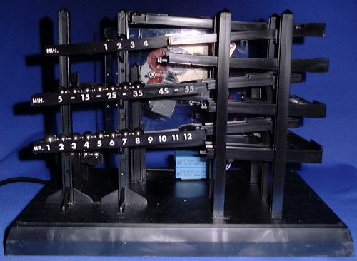
Assembly and some cleaning was all needed to get it working. Then the tuning started to increase its reliability: Some corners cried for smoothing, the little fence on the top rail was added...in the end, it worked (almost) flawlessly in my office for years on end.
Last spring it suddenly stopped. As it turned out, the tiny
motor obviously hadn't survived the continuous abuse by our
recently increased mains voltage (230V now, was 220V
previously).
I mailed Mattel for a replacement part (ok, I HAD to try ;-) but
they never bothered to answer.
So, now I was stuck. Sadly I added "Motor, AC, 220V, 3W, synchronous" to my WANTED list and shelved the clock.
Last autumn fate smiled at me: I found a motor at a surplus trader and couldn't resist the price. But on arrival of the booty I was stuck again: Four wires on the motor, two on my cable... As usual in such situations, my SPLENDID international cavalry - ahem, mailing list came to help and provided the missing spec: The correct phase shifting capacitor was obtained and off I went to the drawing board.
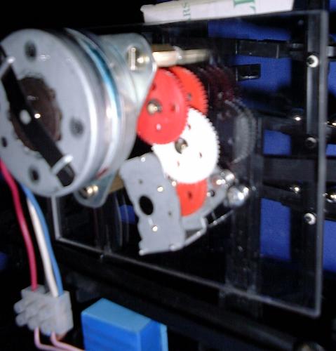
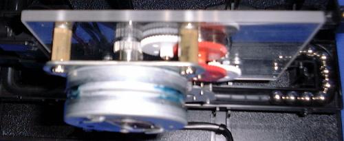
Some gray hairs richer a design was finalized featuring lots of gears (did I mention my fondness of surplus traders ?). I had to drop the idea to hide the mechanism in the little black box which housed the original drive - but on the other hand, why hide running gears at all ?
Well, now it runs again - and this time I have
a spare motor somewhere in my heap...
How could we make the motor run backward ? All we need to do is
invert the polarity sequence of L2, for example by swapping the
leads of the inductor. Another trick with the same result would be
moving the lower connection of V1 (V1-) to the other (right hand
side) end of C1.

Am I disappointed ? No, mine is UNIQUE !