 |
From: Strandh, Sigvart: The History of the Machine,
Dorset Press, New York, 1989 |
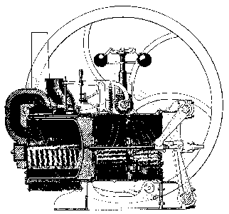
How Ericsson's ultimate caloric engine worked.
The working piston (a) and the feed piston (b) worked
in the same cylinder.
(c) Furnace. A crank mechanism (d) was necessary in order
to make a and b move in a suitable way.
(e) Valve regulated by a disk cam on the crank axle and
connecting the cylinder space (f) with the outside air.
(g) Air-pressure-regulated valves. (h) Holes connecting
cylinder spaces f and (i): uncovered when b moved to the right;
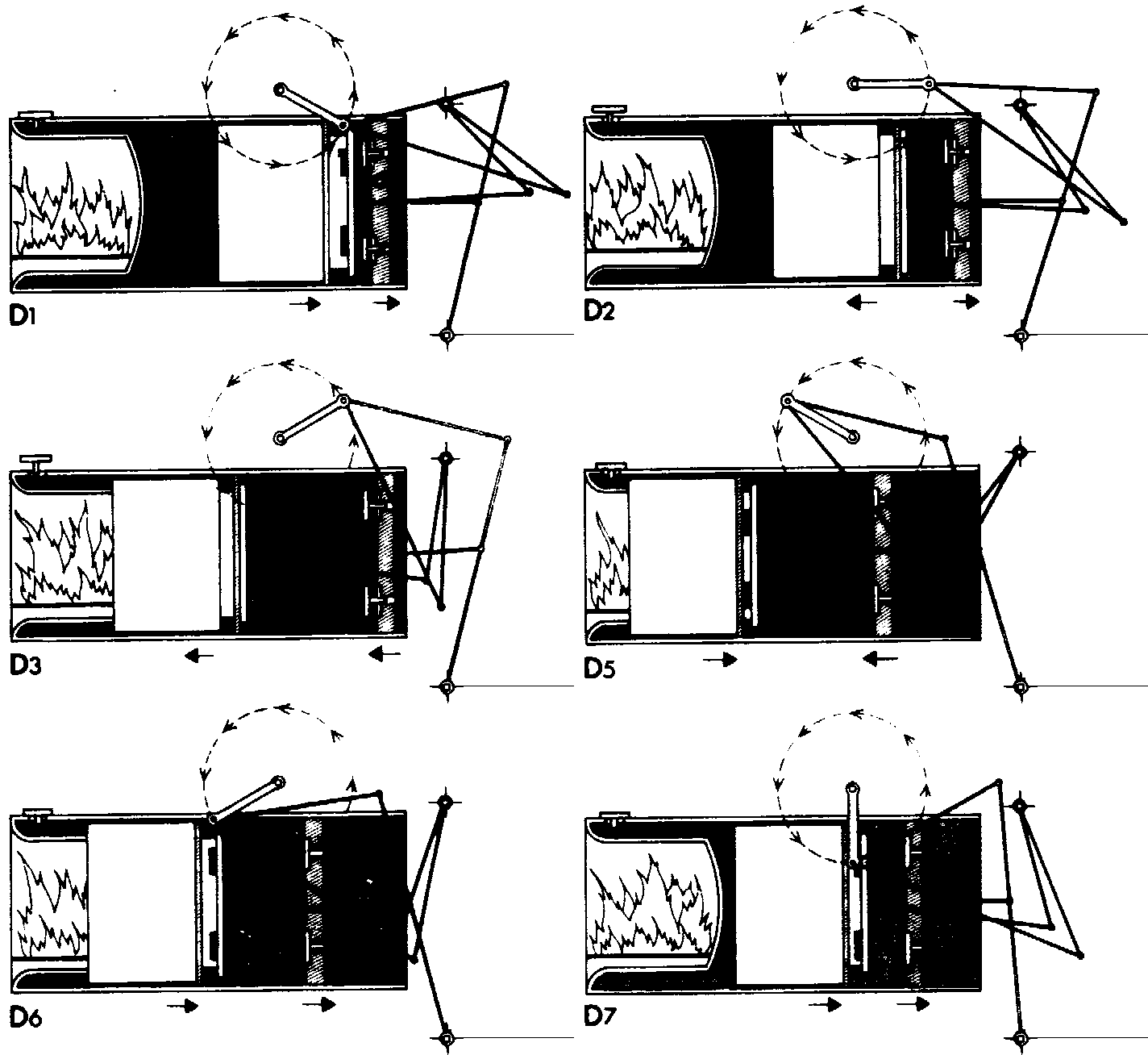
Click on the underlined numbers below to stop the animation in the corresponding
phase; click here to reanimate.

(1) e is closed holes
h are uncovered. Since a moves faster than b, g open, and cold air enters
the cylinder.
(2) Piston b turns,
h are covered, and e is opened so that the air in f can escape.
(3,4)
Piston a turns but moves at a slower speed than b, so valves g remain open.
(5) Piston b turns and
e is closed. The holes (h) are uncovered, and when the air enclosed in
i and f is now heated, its pressure increases, and the valves g close.
(6,7)
The increasing pressure of the air, which becomes hotter and hotter, forces
a to the right.