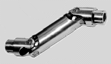
Double Joints
 But let's go back to equation (3). The
misalignment ß could be represented as well by two equal-sized
but smaller angles ß1 and ß2. With an intermediate shaft
turning an angle ð we get:
But let's go back to equation (3). The
misalignment ß could be represented as well by two equal-sized
but smaller angles ß1 and ß2. With an intermediate shaft
turning an angle ð we get:(4) tan(w) = tan(ð) * cos(ß1)
(5) tan(ð) = tan(ø) * cos(ß2)
Simply eliminating ð we get:
(6) tan(w) = tan(ø) * cos2(ß/2)
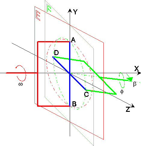
Not much help - oh wait, we missed one important thing: The initial orientation! In the graph above driving shaft angle (w) zero means fork ends A and B on the Z-axis. C and D are therefore sitting on the Y axis in the beginning. If the second joint now would start with its A' and B' on a parallel to C and D, its equation would be different. As we all know (don't we?):
(7) tan(ð+90°) = -1 / tan(ð)
Rotating equation (5) gives
(8) tan(ø) = tan(ð) * cos(ß2)
Now (8) matches (4), which happens to prove - as long as cos(ß1) = cos(ß2)
(9) ø = w
In words: The rotation of the driving and driven shafts is identical at all times when the misalignment angle is ß
a) compensated by two joints,
b) each misaligned by the same angle ß/2 and
c) the intermediate shaft has parallel forks.
Each configuration obeying these rules is called a Constant Velocity Joint (CV).
Applications
 The best known application is the drive shaft in any car.
Here rule b) is interpreted a little more flexible: As driving and
driven shaft are parallel, the two misalignment angles are equal, but
of opposite sign. The cos function in equation (8) mends this
conveniently.
The best known application is the drive shaft in any car.
Here rule b) is interpreted a little more flexible: As driving and
driven shaft are parallel, the two misalignment angles are equal, but
of opposite sign. The cos function in equation (8) mends this
conveniently.© odts 2004
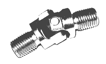
 The most popular type, called Universal Joint, consists of a little
cross. The ends of one cross member are held by the forked end of the
driving
shaft, the other cross member is connected to the driven shaft
likewise.
The center of the cross stays at all times at the exact point where
driving
and driven shaft would intersect were they long enough.
 illustrates this configuration.
For convenience lets adjust a three-dimensionial orthogonal coordinate
system in such a way that the origin is in the center of the cross
(blue), the X axis runs in the core of the driving shaft (red). The
driven shaft (green) finally is kept in the plane defined by axis X
and Z.
 Note:
If you are ambitious, you can obtain exactly the same equation using
spherical geometry. Key is the observation that diameters AB and CD
each
define any number of great circles. Just pick the ones intersecting the
driving
resp. driven shaft. There is only one great circle however containing
all
four points.