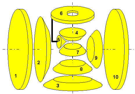
Type "Char montre sud" (CMS) Variant 1 type CMS V1

This design was conceived by Gérard Winkelmuller. He is rightfully very proud of the small number of used gears, especially if.compared to the basic "Lanchester" type. Again a differential put on end is used, mapping to the generic design: Wheel 4 is "left hand side (2)", wheel 7 is "right hand side (1)" and wheel 6 is the "difference (4)". The adapted equation reads
(a:) n7 * rot7 + n4 * rot4 - (n7 + n4) * rot6 = 0
 The other constraints are straight forward:
(b:) rot1 = rot2
(c:) n2 * rot2 + n3 * rot3 = 0
(d:) rot3 = rot4
(e:) rot7 = rot8
(f:) n8 * rot8 + n9 * rot9 = 0
(g:) rot9 = rot10
Composition (POV is from top respectively from far right): <
(j:)(d=>) rot4 = rot3
 (c=>)    = (-1) * (n2 / n3) * rot2
 (b=>)    = (-1) * (n2 / n3) * rot1
(k:)(e=>) rot7 = rot8
 (f=>)    = (-1) * (n9 / n8) * rot9
 (g=>)    = (-1) * (n9 / n8) * rot10
To make it "south-pointing" requires, that if rot10 is held 0, rot6 has to be exactly one turn when wheel 1 of diameter d1 covered one full circle (centre at wheel 10's contact to the ground, radius equal to track width t):
(l:) d1 * rot1 * PI = 2 * t * PI
(m:) rot6 = 1
(n:) rot10 = 0
(k=>) rot7 = 0
(a=>) n7 * 0 + n4 * rot4 - (n7 + n4) * 1 = 0
(=>o:) rot4 = (n7 + n4) / n4
(j=>) rot1 = (-1) * (n3 / n2) * (n7 + n4) / n4
(l=>) | d1 | = 2 * t * (n2 / n3) * (n4 / (n7 + n4))
The same method can be applied to calculate the required size for wheel 10: If rot1 is held 0, rot6 has to be exactly one turn when wheel 10 of diameter d10 covered one full circle (this time centre at wheel 1's contact to the ground, radius equal to track width t):
(p:) d10 * rot10 * PI = 2 * t * PI
(q:) rot1 = 0
(j=>) rot4 = 0
(a=>) n7 * rot7 + n4 * 0 - (n7 + n4) * 1 = 0
(=>r:) rot7 = (n4 + n7) / n7
(k=>) rot10 = (n8 / n9) * (n4 + n7) / n7
(p=>) d10 = 2 * t * (n9 / n8) * (n7 / (n4 + n7))

Given Parameters (Your choice !)

Reference
Size Description
2
n2[teeth] Bevel gear, fixed to wheel 1
3
n3[teeth] Bevel gear, fixed to vertical shaft
4
n4[teeth] Bevel gear, fixed to vertical shaft
5
n5 = [teeth] Bevel gear, freerunning on short shaft, which in turn is fixed to platform 6
6
- Platform, freerunning on central vertical shaft
7
n7 = [teeth] Bevel gear, freerunning on vertical shaft
8
n8 = [teeth] Bevel gear, fixed to wheel 7
9
n9 = [teeth] Bevel gear, fixed to wheel 10
T
t = [length units] Track width

Derived Parameters

Reference
Size Description
1
d1[units of t] Roadwheel, freerunning on halfaxle
10
d10[units of t] Roadwheel, freerunning on halfaxle

© odts 2009