| (1) | n1 * rot1 = n2 * rot2 * (-1) or n1 * rot1 + n2 * rot2 = 0 |
| (2) | Formula (1) is valid only if rot is measured relative to the POC. |
| (3) | rot = wrot + drot |
Make sure the three rules given so far are understood. If insecure grab some gear wheels and play with them! Or try your skills with example 1 further down.
In the following we will prove all this from the three basic rules
given in the beginning and best of all, derive some simple equations to
calculate the behavior from gear sizes only.
In the context considered here (the POV principle, you remember ?) the
horizontal shafts are assumed to be fixed to some structure, i.e. they
can not move round when the wheels are turned. This can be put down
formally
as
(a) drot4
= 0
For the reversal mode, wheel 4 is blocked, so wheel 3's shaft is unable
to move as well. We state (note the upper case letter in the bracket)
(A) drot3
= 0
The rest is quite simple. Bevel gears very much behave like spur gears:
(b) n1 * wrot1
+ n3 * wrot3 = 0
(c) n2 * wrot2
+ n3 * wrot3 = 0
But wait - what about the angle between the shafts ? As long as
your POV is relative to each single wheel, that doesn't matter. We are
allowed to calculate
(d) n1 * wrot1
- n2 * wrot2 = 0
if we define the direction of rotation by looking down on the wheel,
i.e. from the very right for wheel 1 but from left for wheel 2. If we
normalize our POV to the direction of wheel 1, we have to look at wheel
2 from the other face, which exactly reverses its direction ! So we
finally get:
(B) n1 * wrot1
+ n2 * wrot2 = 0
which is nothing else than the formal definition of Reversal
!
Now block wheel 2 and do the string trick introduced for rule (2):
Tie the string round the shaft of wheel 2 and the horizontal part of
the kinked shaft of wheel 3. The observation will show (remember to
look at all wheels from the same POV, e.g. far right) that
(e) wrot4
= drot2
(C) n3 * drot3
+ n2 * drot2 = 0
Same experiment with wheel 1:
(f) wrot4
= drot1
At this point we boldly add up all equations we like (n1*f +n2*e+B+(n1+n2)*a):
(g) n1 * (drot1
+ wrot1) + n2 * (drot2
+ wrot2) = (n1 + n2) * (drot4
+ wrot4)
Formally applying the superposition rule (3) reveals the universal
equation for differentials:
| (4) | n1 * rot1 + n2 * rot2 - (n1 + n2) * rot4 = 0 |
Reduction now is a simple to understand: Set rot2
to 0 and (D) becomes
(E) rot4 = rot1/2
Differential is no harder: Set rot2 =
-rot1 + delta and you get
(F) rot4 = delta/2
Some more observations:
 If you look under the rear of a lorry you most probably will will see
a thick "blob" in the middle of the rear axle, with three shafts
entering
to it: The axle to the left rear wheel, the axle to the right rear
wheel
and the drive shaft to somewhere in front of the axle. This "blob"
contains
nothing more than the differential described in the previous chapter
plus
one more bevel gear (5), which imparts the drive shaft's rotation to
wheel
4, now also beveled. As we know by now, with a POV from right for wheel
4
and above for wheel 5 we can put down:
If you look under the rear of a lorry you most probably will will see
a thick "blob" in the middle of the rear axle, with three shafts
entering
to it: The axle to the left rear wheel, the axle to the right rear
wheel
and the drive shaft to somewhere in front of the axle. This "blob"
contains
nothing more than the differential described in the previous chapter
plus
one more bevel gear (5), which imparts the drive shaft's rotation to
wheel
4, now also beveled. As we know by now, with a POV from right for wheel
4
and above for wheel 5 we can put down:  (G) rot1 + rot2
= k * rot5
(G) rot1 + rot2
= k * rot5 
 (H) rot1 + rot2
= - k * rot5
(H) rot1 + rot2
= - k * rot5 
n1 * wrot1 + n2 * wrot2 = 0Eliminating n2 (e.g. by subtracting the second line) results in
n2 * wrot2 + n3 * wrot3 = 0
n1 * wrot1 - n3 * wrot3 = 0or in other words, wheels 1 and 3 rotate in the same direction.
Wheels 3 and 6 are both fixed to a common shaft.
(a) rot3 = rot6Wheel 1 is the power input and meshes with transfer wheel 2, which runs freely on the axle.
(b) n1 * wrot1 + n2 * wrot2 = 0Both wheels' shafts are attached to the vehicle.
(c) drot1 = drot2 = 0Wheel 4 is an idler and the left road wheel is attached to wheel 5.
(d) n5 * wrot5 - n3 * wrot3 = 0The right road wheel is attached to wheel 7.
(e) n7 * wrot7 + n6 * wrot6 = 0And now the trick: The shaft of wheels 3 and 6 is bushed in transfer wheel 2, so when wheel 2 turns with the shaft locked:
(f) drot5 = drot7 = wrot2The superposition rule (3) decrees:
(g) rot5 = drot5 + wrot5Putting all this through the math mill gives:
(h) rot7 = drot7 + wrot7
(h:) rot7 = drot7 + wrot7Setting all ratios to 1 results in
(e:) = drot7 - (n6/n7) * wrot6
(a:) = drot7 - (n6/n7) * wrot3
(d:) = drot7 - (n6/n7) * (n5/n3) * wrot5
(g:) = drot7 - (n6/n7) * (n5/n3) * rot5 + (n6/n7) * (n5/n3) * drot5
(f:) = wrot2 - (n6/n7) * (n5/n3) * rot5 + (n6/n7) * (n5/n3) * wrot2
= ( 1 + (n6/n7) * (n5/n3)) * wrot2 - (n6/n7) * (n5/n3) * rot5
(b:) = (-1) * {( 1 + (n6/n7) * (n5/n3) * (n1/n2) * wrot1 + (n6/n7) * (n5/n3) * rot5 }(c:) (n7/n6) * rot7 + (n5/n3) * rot5 + {(n7/n6) + (n5/n3)} * (n1/n2) * rot1 = 0
rot7 + rot5 + 2 * rot1 = 0Sounds familiar? Don't worry about the sign mismatch to rule (4) - another spur wheel or starting at wheel 2 will fix this easily.
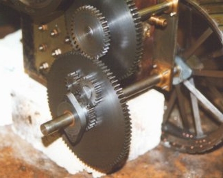
| Last not least it shall be
mentioned that the spur wheel differential can be built "boxed" as
well: The central drive wheel (2) is replaced by a drum enclosing the
complete mechanism. (2) now being out of the way, wheels (3) and (6)
can be
merged. To cater for higher forces any number of pairs ((4),(3+6)) can be put into the box. |
 |