Type "ODTS 3"type odts3

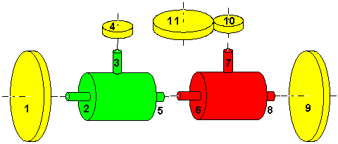
The next escalation of my "car recycling project" with Ian White is this two differential design. This time the reversal of the left wheel is done by clamping solid the left differential's drive shaft entry. The only gears needed are used to compensate the reduction ratio of the right (inverse!) differential. The dimensioning equations:
(a:) rot2 + rot5 - k * rot3 = 0
(b:) rot6 + rot8 + k * rot7 = 0
(c:) n10 * rot10 + n11 * rot11 = 0
 The remaining constraints:
(d:) rot1 = rot2
(e:) rot3 = rot4 = 0
(f:) rot5 = rot6
(g:) rot8 = rot9
(h:) rot7 = rot10
Composition
(a,d,e,f=>i) rot6 =  - rot1
(b,g,i=>j) rot10 =  (rot1 - rot9) / k
(c,j=>k) rot11 = (rot9 - rot1) * (n10 / n11) / k
To make it "south-pointing" requires, that if rot1 is held 0, rot11 has to be exactly one turn when wheel 9 of diameter d9 covered one full circle (centre at wheel 1's contact to the ground, radius equal to track width t):
(l:) d9 * rot9 * PI = 2 * t * PI                                                     d1 * rot1 * PI = 2 * t * PI
(m:) rot1 = 0
rot9 = 0
(n:) rot11 = 1
rot11 = -1
(k=>) rot9 = k * (n11 / n10)
rot1 = k * (n11 / n10)
(l=>) d9 = 2 * t / rot9
d1 = 2 * t / rot1
The same method can be applied to calculate the required size for wheel 1, see rightmost column of table above.

Given Parameters (Your choice !)

Reference
Size Description
10
n10[teeth] Spur gear, fixed to drive shaft 7 of differential
11
n11[teeth] Spur gear, fixed to pointer
k
k =  Differential reduction factor
T
t = [length units] Track width

Derived Parameters

Reference
Size Description
1
d1[units of t] Road wheel, free running on axle
9
d9[units of t] Road wheel, free running on axle

© odts 2002