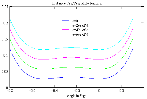
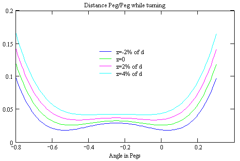
Again some elementary math will provide the dependency
of the minimum distance from N1, N2, e and z. The distance is given
by
(6)
with
(7) f = d*(1 + e/200) e given in % of d
(8) g = 2*z / (200 + e) e and z given in % of d
To find the absolute minimum this needs to be differentiated and the roots found. The relevant part of the differential dt is
(9)
Again I couldn't find a simple solution. The following graphs shall give a qualitative understanding of the results, while the approximate value for each set of he four parameters can be requested from the Calculation Sheet (requires Javascript enabled in Your browser).
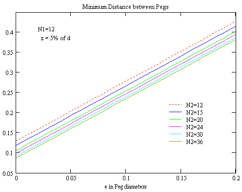
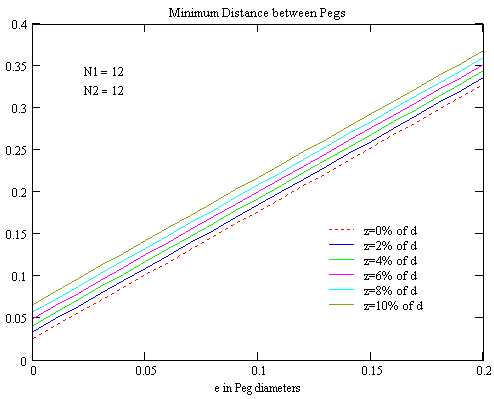
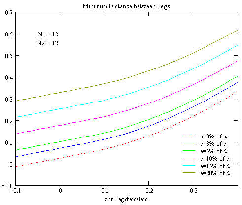
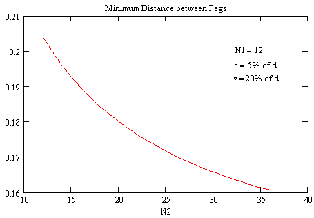
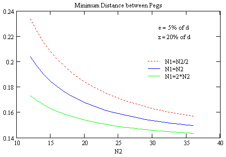
(6)

with
(7) f = d*(1 + e/200) e given in % of d
(8) g = 2*z / (200 + e) e and z given in % of d
To find the absolute minimum this needs to be differentiated and the roots found. The relevant part of the differential dt is
(9)

Again I couldn't find a simple solution. The following graphs shall give a qualitative understanding of the results, while the approximate value for each set of he four parameters can be requested from the Calculation Sheet (requires Javascript enabled in Your browser).


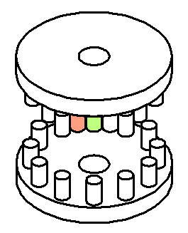 The turning axles of the two wheels are parallel. It should be obvious
that this use case is not ideal, as the point of contact jumps back and
forth (we will see this further down), but if just an idler is needed it
may be acceptable.
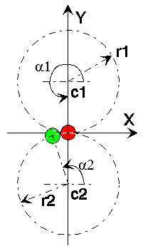 The fundamental idea behind all kinds of gearing is the equivalence
between two ratios: The ratio of the numbers of teeth is inversely proportional
to the number of turns for every pair of meshing gears. Using this rule,
the coordinate system shown right and looking at the pitch circles (the
circle the centers of the pegs are located on), we can write down the equations
for each peg: